Sniffing I2C Communications
Introduction#
A variety of hardware is available to interface and sniff I2C communications. These devices range in capabilities, from basic logic analyzers to more complex devices that permit injecting data into the bus.
Summary of hardware used#
- Adafruit Stemma QT PCT-2075 (Datasheet 1)
- Sparkfun Logic Analyzer
- Generic ESP-8266 module
The Inter-Integrated Circuit Bus (I2C) is a common protocol that allows a microcontroller to interact with some peripheral component. This allows a number of devices to be connected in parallel using only 4 wires.
- power
- ground
- serial data line (SDA)
- serial clock line (SCL)
When the microcontroller wants to speak with a specific device, a 7 bit address is used, plus an additional bit to specify whether it is a read or write operation.
Based on the documentation, the temperature sensor resides at address 0x37. When a read operation is requested, the microcontroller will send the 7 bit address with another bit specifying whether a read or write operation is occuring, followed by one or more bytes which indicate which register is to be read. After the peripheral device acknowledges the transmission, the microcontroller will send the address bit with the corresponding read flag.
This will be shown in detail next.
Sniffing I2C#
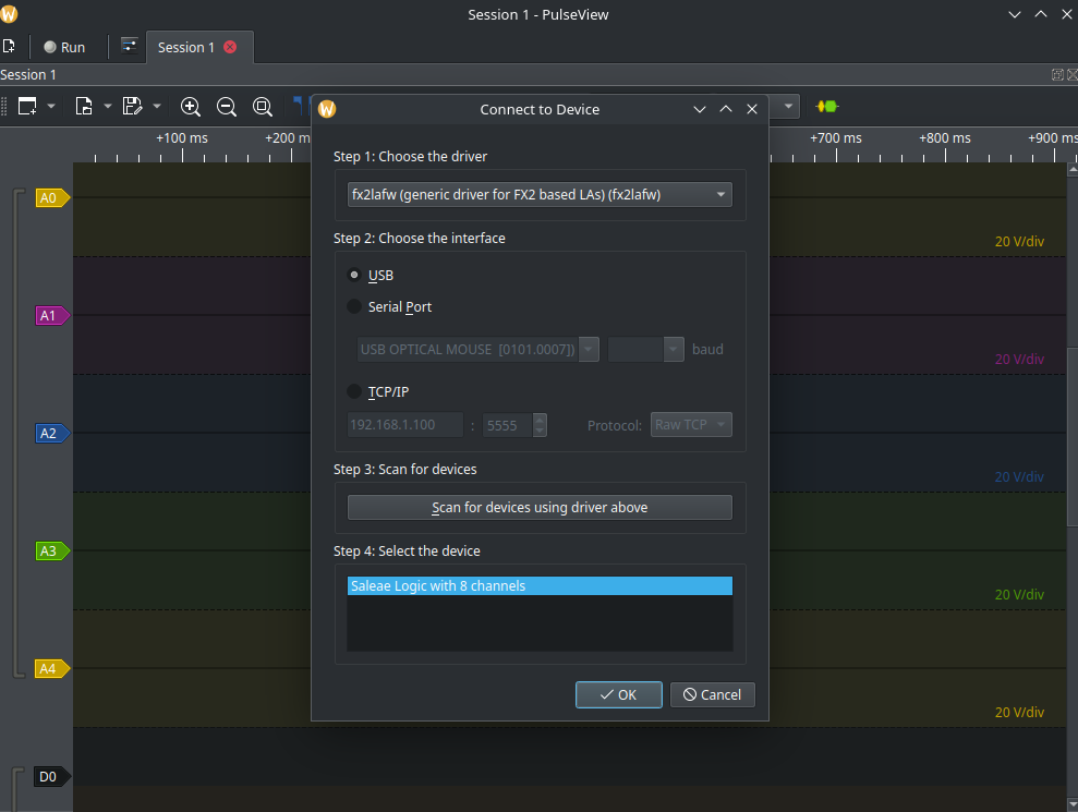
First, I connected the logic analyzer to my computer and configured as shown.

The driver is fx2lafw and is automatically detected with the scan.
A Stemma QT to dupont wire adapter was used to connect the power, ground, and data lines to the logic analyzer.
#the image
| Logic Analyzer Pin | Device Pin | Description |
|---|---|---|
| 0 | VCC | Sensor Power |
| 1 | SCL | Serial Clock |
| 2 | SDA | Serial Data |
| 3 | RST | Microcontroller reset |
| 16 | GND | Ground |
The reason for adding the microcontroller reset pin is to trigger the data collection in pulseview.
Within pulseview, I renamed D1 and D2 with the labels SCL and SDA respectively. I also applied a the trigger the capture start on D3. I also added the I2C decoder from the right hand panel. The capture settings are set to 2M samples, with a sample rate of 1Mhz. This will result in the logic analyzer recording 2 seconds worth of data after the reset button is pressed.
With the connections and configuration complete, it’s time to capture the signals.
Capturing#
After clicking the run button, I pressed the reset button on the microcontroller to start the data capture.

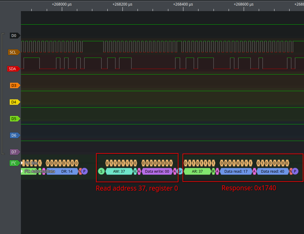
After the microcontroller performs the initial setup of the sensor, it reads the data from the temperature sensor once every second.
The read/write flag within the I2C messaging is counterintuitive (at least to me). The first highlighted sequence is a write operation. This instructs the peripheral device that register 0 will be read from. This could equally be register 1, or 3 as required. These additional registers contain configuration values like high/low temperature alerts.
The second block is the actual read command. The data comes back as two bytes, 0x17 and 0x40. This can be combined into 0x1740. This can be converted to a decimal number by following the instructions in the data sheet.
First, 0x1740 gets shifted 5 bits to the right. This becomes the integer value 186. Multiplied by .125, this becomes 23.25 degrees Celcius.
The microcontroller code#
The arduino code loaded on the microcontroller is relatively simple and is based off the example code provided by Adafruit.
References#
-
PCT 2075 Datasheet, NXP Semiconductors ↩︎